Chemical Etching
Metal Fabrication
Managing tolerances is one of the most overlooked drivers of cost and delay in precision metal manufacturing. Engineers often specify aggressive tolerances with good intent. They want performance. They want repeatability. Yet those decisions can introduce avoidable issues when they are not tied directly to function.
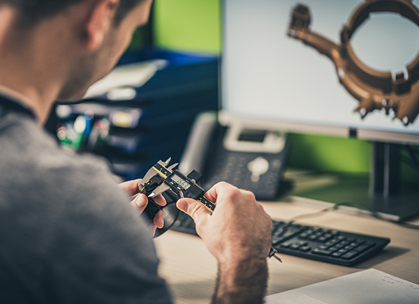
In early design stages, tolerance choices influence yield, lead time, inspection effort, and readiness for scale. Poor decisions early tend to resurface later as schedule pressure and cost growth.
Tolerance strategy should start with performance, not habit. Many drawings inherit tight callouts from legacy designs or internal defaults. Others apply blanket limits across an entire part. These practices rarely improve outcomes. Instead, they increase scrap rates and slow production. Inspection time grows. Rework becomes common. A focused approach identifies which features actually control performance. Everything else should be allowed to vary within practical process limits.
Overly tight or poorly defined tolerances drive unnecessary cost without improving reliability. They also reduce flexibility during prototyping. A thoughtful strategy improves yield, shortens lead times, and supports smoother transitions into higher volumes.
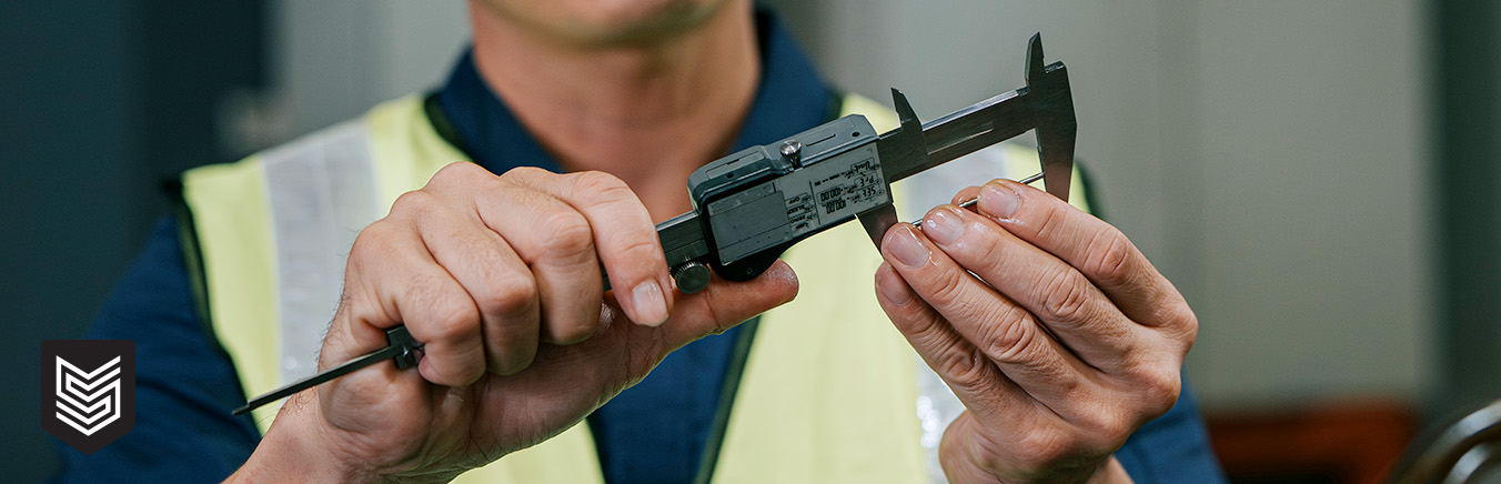
Photochemical Machining, or PCM, behaves differently from stamping or laser cutting. It is a chemical material removal process. There is no mechanical force. There is no heat input. That means no burrs, no tool wear, and no induced stress. These characteristics make PCM highly repeatable and well-suited for early-stage development. They also affect how tolerances should be planned.
PCM tolerances are influenced by material type, thickness, feature geometry, and etch depth. Sheet size and panel layout matter as well. Post-processing steps, such as forming or plating, can add variation. None of these factors is unpredictable, but they must be considered during design. Engineers who understand these behaviors can align tolerance intent with process capability.
Material choice plays a role in tolerance behavior. Stainless steels, copper alloys, and nickel alloys etch at different rates. Thickness also matters. As the material gets thicker, the etch depth increases and the tolerance windows shift. Feature geometry affects outcomes, too. Narrow webs and fine apertures behave differently from larger features. Long straight edges respond differently from small cutouts.
Because PCM removes material evenly from both sides, dimensional change is predictable. This allows engineers to plan tolerances that are realistic and repeatable. Designs that account for these traits are easier to prototype and easier to scale.
 Common Tolerance Traps in PCM Designs
Many PCM-related cost and schedule issues trace back to a small set of recurring tolerance mistakes that appear early in design and compound as programs move forward:
Effective tolerance planning focuses on a few principles. Identify critical-to-function features early. Define tolerance intent during prototyping, not after. Separate cosmetic requirements from functional ones. Align tolerances with inspection and post-processing plans. This approach supports predictable cost and smoother scale-up.
Switzer applies an engineering-first perspective to tolerance strategy, helping teams use PCM effectively while balancing performance and manufacturability from early design through production.
4020 Jeffrey Blvd. | BUFFALO, NY 14219
P: (716) 821-9393 / (800) 875-1093
Website by Luminus